Due Date
Wed Mar 16th, 11:59pm
Additional Notes
In addition to the writeup below, these supplemental notes may be useful in guiding your implementation. (Note that you do not have to handle surfaces with boundary, unless you are shooting for extra credit!)
- Correctly Implementing Edge Flip/Split/Collapse
- Edge Operations on an Oriented Triangle Mesh
- Conventions for Meshes with Boundary
Overview
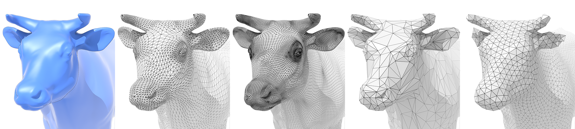
In this project you will implement a simple mesh editor that allows you to manipulate and resample triangle meshes. When you are done, you will have a tool that allows you to load and edit basic COLLADA mesh files that are now used by many major modeling packages and real time graphics engines. (You can create your own COLLADA files in free software like Blender.)
Getting started
We will be distributing assignments with git. You can find the repository for this assignment at http://462cmu.github.io/asst2_meshedit/. If you are unfamiliar with git, here is what you need to do to get the starter code:
$ git clone https://github.com/462cmu/asst2_meshedit.git
This will create a asst2_meshedit folder with all the source files.
Build Instructions
In order to ease the process of running on different platforms, we will be using CMake for our assignments. You will need a CMake installation of version 2.8+ to build the code for this assignment. The GHC 5xxx cluster machines have all the packages required to build the project. It should also be relatively easy to build the assignment and work locally on your OSX or Linux. Building on Windows is currently not supported.
If you are working on OS X and do not have CMake installed, we recommend installing it through Macports:
sudo port install cmake
Or Homebrew:
brew install cmake
To build your code for this assignment:
- Create a directory to build your code:
$ cd asst2_meshedit && mkdir build && cd build
- Run CMake to generate makefile:
$ cmake ..
- Build your code:
$ make
- Install the executable (to asst2_meshedit/bin):
$ make install
Using the MeshEdit App
When you have successfully built your code, you will get an executable named meshedit. The meshedit executable takes exactly one argument from the command line. You may load a single COLLADA file by specifying its path. For example, to load the example file dae/quadball.dae from your build directory:
./meshedit ../dae/quadball.dae
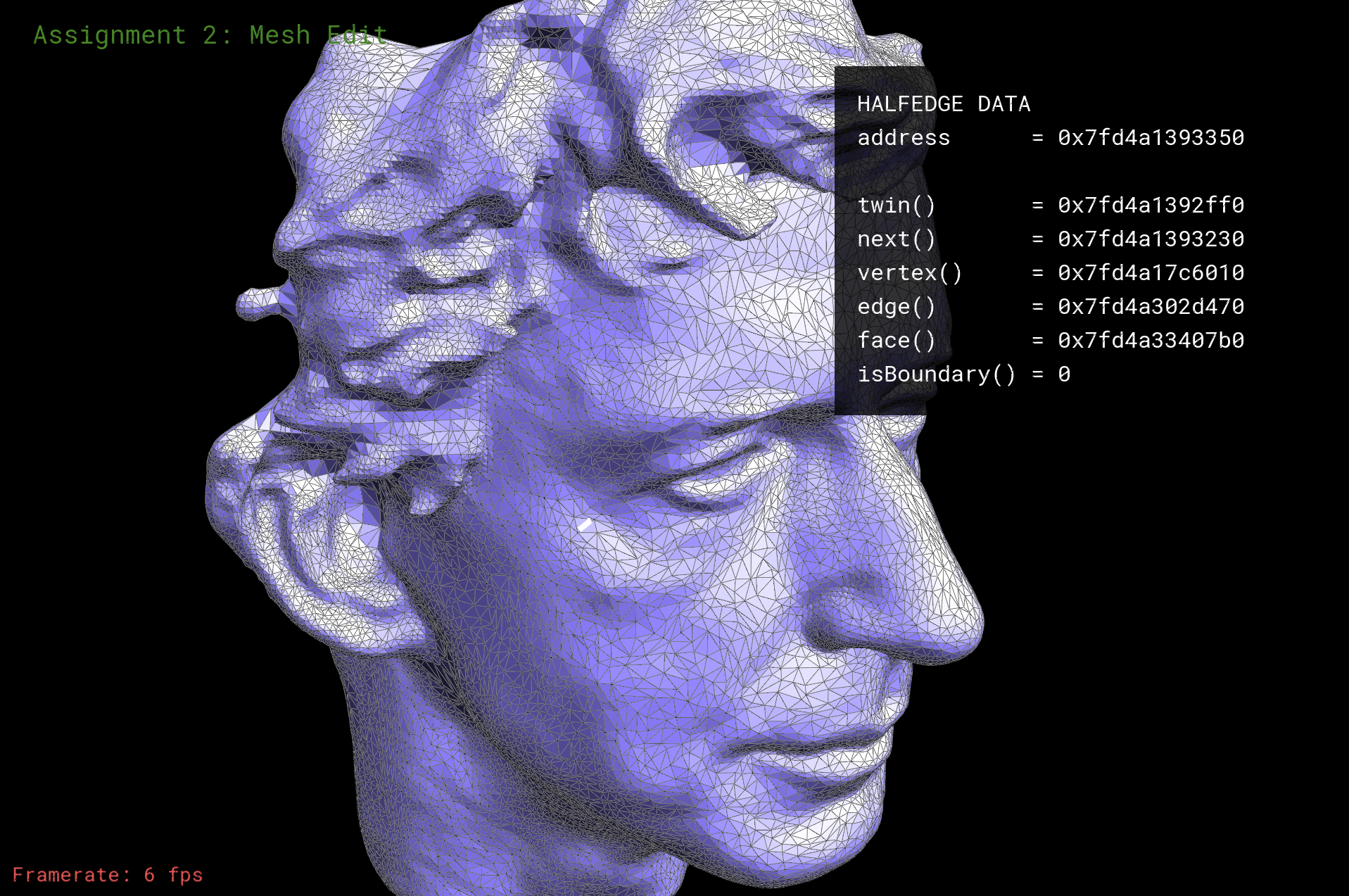
When you first run the application, you will see a picture of a mesh made of triangles. The starter code that you must modify is drawing this mesh. The editor already supports some basic functionality, like moving vertices around in space, which you can do by just clicking and dragging on a vertex. You can also rotate the camera by right-clicking and dragging (or dragging on the background), and zoom in and out using the scroll wheel or multi-touch scrolling on a trackpad. Hitting the spacebar will reset the view. As you move the cursor around the screen, you'll notice that mesh elements (faces, edges, and vertices) under the cursor get highlighted. Clicking on one of these elements will display some information about the element and its associated data.
In this assignment, you will add additional functionality to the program that allows you to modify the mesh in a variety of ways. Each of these methods is exposed through the viewer. There will be two basic types of operations:
- (FIRST WEEK) Local resampling - modifies the mesh in a small neighborhood around the currently selected mesh element.
- (SECOND WEEK) Global resampling - modifies the entire mesh, in an effort to improve the overall quality, size, etc.
Each operation will be executed with a key press (see table below).
'f' - flip the currently selected edge 's' - split the currently selected edge 'c' - collapse the currently selected edge 'u' - upsample the mesh 'd' - downsample the mesh 'r' - resample the mesh
Notice that currently, nothing happens when keys are pressed - this is because you haven't yet implemented resampling! Unlike the previous assignment, no reference solution is provided. However, we will provide several examples of correct input/output pairs for each remeshing operation.
Note that each COLLADA file may contain multiple mesh objects; more generally, a COLLADA file describes a scene graph (much like SVG) that is a hierarchical representation of all objects in the scene (meshes, cameras, lights, etc.), as well as their coordinate transformations. Global resampling methods will be run on whichever mesh is currently selected.
Summary of Viewer Controls
A table of all the keyboard controls in the meshedit application is provided below.
| Command | Key |
|---|---|
| Flip the selected edge | F |
| Split the selected edge | S |
| Collapse the selected edge | C |
| Upsample the current mesh | U |
| Downsample the current mesh | D |
| Resample the current mesh | R |
| Toggle information overlay | I |
| Reset camera to default position | SPACE |
| Select the next halfedge | N |
| Select the twin halfedge | T |
| Edit a vertex position | (click and drag on vertex) |
| Rotate camera | (click and drag on background, or right click) |
What You Need to Do
The assignment is divided into two major components: local operations and global operations; the latter will build on the former (e.g., local edge collapses will ultimately be used for global downsampling). As with the previous assignment, this assignment involves significant implementation effort. Also, be advised that to meet the requirements of later tasks, you should be sure that your local operations handle corner cases; it won't be enough to work only on simple examples! In short: you are highly advised to complete the first component before the midterm, and carefully consider the correctness of your code, since it will be used later for more complicated tasks. Specifically, you should handle corner cases properly in all your edge operations to maintain the manifoldness of the mesh because global operations will depend on the correctness of your local operations.
NOTE: The second component (global remeshing) depends on concepts that will be discussed in lectures on geometry processing, so it is not expected that you understand those requirements at the time this assignment is released.
Getting Acquainted with the Starter Code
Before you start, here are some basic information on the structure of the starter code.
Your work will be constrained to implementing part of the classes HalfedgeMesh and MeshResampler in student_code.cpp. Although the halfedge data structure is designed to support general polygon meshes, you can assume that all meshes used in this assignment will be made of triangles only. You can also assume that the input mesh is manifold, possibly with boundary, i.e., that each edge is contained in at most two polygons (or one polygon if it is on the boundary), and each vertex is connected to a single "fan" of triangles. Note that the atomic remeshing operations (split, collapse, and flip) are supposed to preserve the manifold property of the mesh---but it is only your own implementation that can provide this guarantee! In other words, if you make a mistake in one of the local remeshing operations, it can cause trouble for other routines later down the line (probably causing your program to crash!).
The Halfedge Data Structure
For simple mesh operations (e.g., loading a mesh from disk and drawing it on screen), one can use a very simple mesh data structure like polygon soup, i.e., just a list of vertices together with a list of polygons connecting them. For many geometry processing tasks, however, this simple representation is no longer sufficient (or leads to unnecessarily bad asymptotic performance). In this assignment, we use the halfedge data structure, which provides a good tradeoff between simplicity and sophistication.
The basic idea behind the halfedge data structure is that, in addition to the usual vertices, edges, and faces that make up a polygon mesh, we also have an entity called a halfedge that acts like a "glue" connecting the different elements. It is this glue that allows us to easily navigate the mesh.
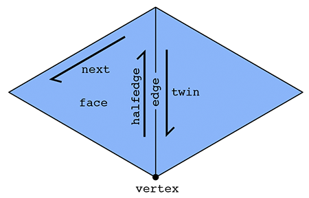
In particular, there are two halfedges associated with each edge (see picture above). For an edge connecting two vertices i and j, one of its halfedges points from i to j; the other points from j to i. In other words, we say that the two halfedges are oppositely oriented. One of the halfedges is associated with the face to the "left" of the edge; the other is associated with the face to the "right." Each halfedge knows about the opposite halfedge, which we call its twin. It also knows about the next halfedge around its face, as well as its associated edge, face, and vertex.
In contrast, the primitive mesh elements (vertices, edges, and faces) know about only one of their halfedges. In particular: a vertex knows about one of its "outgoing" halfedges; an edge knows about one of its two halfedges; and a face knows about one of the halfedges circulating around its interior.
In summary, we have the following relationships:
| Mesh element | Pointers |
|---|---|
| Vertex | one halfedge |
| Edge | one halfedge |
| Face | one halfedge |
| Halfedge | twin, next, vertex, edge, face |
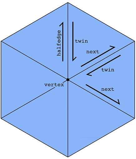
This list emphasizes that it is really the halfedges that connect everything up. An easy example is if we want to visit all the vertices of a given face. We can start at the face's halfedge, and follow the "next" pointer until we're back at the beginning. A more interesting example is visiting all the vertices adjacent to a given vertex v. We can start by getting its outgoing halfedge, then its twin, then its next halfedge; this final halfedge will also point out of vertex v, but it will point toward a different vertex than the first halfedge. By repeating this process, we can visit all the neighboring vertices:
(Can you easily do this traversal with a polygon soup? Why or why not?) In some sense, a halfedge mesh is kind of like a linked list on steroids. For instance, the halfedges around a given face (connected by next pointers) form a sort of "cyclic" linked list, where the tail points back to the head.
An interesting consequence of the halfedge representation is that any valid halfedge mesh must be manifold and orientable. In this assignment, we will therefore only provide manifold, oriented meshes as input (in fact, the parser will complain if the input does not satisfy these criteria).
The HalfedgeMesh Class
For this assignment, we've already provided a C++ implementation of the halfedge data structure. Although the detailed implementation might appear a bit intimidating at first (especially if you haven't had much experience with C++), the basic interface you'll need for this assignment is not much different from the abstract description given above. For instance, suppose we have a face f and want to print out the positions of all its vertices. We would write a routine like this:
void printVertexPositions( FaceCIter f )
{
   HalfEdgeCIter h = f->halfedge(); // get the first halfedge of the face
   do
   {
      VertexCIter v = h->vertex(); // get the vertex of the current halfedge

      cout << v->position << endl; // print the vertex position

      h = h->next(); // move to the next halfedge around the face
   }
   while( h != f->halfedge() ); // keep going until we're back at the beginning
}
(For an explanation of the low-level details (e.g., why do we call it a FaceCIter rather than just a Face?), see the inline documentation in the code, or the corresponding Doxygen documentation.) Similarly, to print out the positions of all the neighbors of a given vertex we could write a routine like this:
void printNeighborPositions( VertexCIter v )
{
   HalfEdgeCIter h = v->halfedge(); // get one of the outgoing halfedges of the vertex
   do
   {
      HalfEdgeCIter h_twin = h->twin(); // get the vertex of the current halfedge
      VertexCIter v = h_twin->vertex(); // vertex is 'source' of the half edge.
                                        // so h->vertex() is v,
                                        // whereas h_twin->vertex() is the neighbor vertex.

      cout << v->position << endl; // print the vertex position

      h = h_twin->next(); // move to the next outgoing halfedge of the vertex.
   }
   while( h != v->halfedge() ); // keep going until we're back at the beginning
}
To iterate over all the vertices in a halfedge mesh, we could write a loop like this:
for( VertexCIter v = mesh.verticesBegin(); v != mesh.verticesEnd(); v++ )
{
   printNeighborPositions( v ); // do something interesting here
}
Internally, the lists of vertices, edges, faces, and halfedges are stored as linked lists, which allows us to easily add or delete elements to our mesh. For instance, to add a new vertex we can write
VertexIter v = mesh.newVertex();
Likewise, to delete a vertex we can write
mesh.deleteVertex( v );
Note, however, that one should be very, very careful when adding or deleting mesh elements. New mesh elements must be properly linked to the mesh---for instance, this new vertex must be pointed to one of its associated halfedges by writing something like
v->halfedge() = h;
Likewise, if we delete a mesh element, we must be certain that no existing elements still point to it; the halfedge data structure does not take care of these relationships for you automatically. In fact, that is exactly the point of this assignment: to get some practice directly manipulating the halfedge data structure. Being able to perform these low-level manipulations will enable you to write useful and interesting mesh code far beyond the basic operations in this assignment.
Finally, the boundary of the surface (e.g., the ankles and waist of a pair of pants) requires special care in our halfedge implementation. At first glance, it would seem that the routine printNeighborPositions() above might break if the vertex v is on the boundary, because at some point we worry that we have no twin() element to visit. Fortunately, our implementation has been designed to avoid this kind of catastrophe. In particular, rather than having an actual hole in the mesh, we create a "virtual" boundary face whose edges are all the edges of the boundary loop. This way, we can iterate over boundary elements just like any other mesh element. If we ever need to check whether an element is on the boundary, we have the methods.
Vertex::isBoundary()
Edge::isBoundary()
Face::isBoundary()
Halfedge::isBoundary()
These methods return true if and only if the element is contained in the domain boundary. Additionally, we store an explicit list of boundary faces, which we can iterate over like any other type of mesh element:
for( FaceCIter b = mesh.boundariesBegin(); b != mesh.boundariesEnd(); b++ ) { // do something interesting with this boundary loop }
These virtual faces are not stored in the usual face list, i.e., they will not show up when iterating over faces.
Please refer to the inline comments (or the Doxygen documentation) for further details.
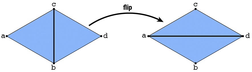
Task 1 : Edge Flip
In this task you will implement a local remeshing operation that "flips" an edge, by implementing the method HalfedgeMesh::flipEdge in student_code.cpp. In particular, suppose we have a pair of triangles (a,b,c) and (c,b,d). After flipping the edge (b,c), we should now have triangles (a,d,c) and (a,b,d):
In more detail, your solution should:
- Ignore requests to flip boundary edges (just return immediately if either neighboring face is a boundary loop).
- Ignore requests to perform any edge flip that would make the surface non-manifold or otherwise invalidate the mesh.
- Perform only a constant amount of work---the cost of flipping a single edge should not be proportional to the size of the mesh!
- Not add or delete any elements. Since there are the same number of mesh elements before and after the flip, you should only need to reassign pointers.
Formally proving that your code preserves manifoldness in all cases may be challenging, but at least try to think about what could go wrong in degenerate cases (e.g., vertices of low degree, or very small meshes like a tetrahedron). The biggest challenge in properly implementing this operation (as well as collapse and split) is making sure that all the pointers still point to the right place in the modified mesh. An easy recipe for ensuring that all pointers are still valid after a remeshing operation is:
- Draw a picture and/or write down a list of all the elements (vertices, edges, faces, halfedges) that will be needed from the original mesh.
- Draw a picture and/or write down a list of all the elements that should appear in the modified mesh.
- Allocate any new elements that are needed in the modified mesh, but do not appear in the original mesh.
- For every element in the "modified" picture, set all of its pointers---even if they didn't change. For instance, for each halfedge, make sure to set
next,twin,vertex,edge, andfaceto the correct values in the new (modified) picture. For each vertex, make sure to set itshalfedgepointer. Etc. A convenience methodHalfedge::setNeighbors()has been created for this purpose. - Deallocate any elements that are no longer used in the modified mesh, which can be done by calling
HalfedgeMesh::deleteVertex(),HalfedgeMesh::deleteEdge(), etc.
The reason for setting all the pointers (and not just the ones that changed) is that it is very easy to miss a pointer, causing your code to fail. Once the code is working, you can remove these unnecessary assignments if you wish---but remember that premature optimization is the root of all evil
Possible Extra Credit Extensions:
Define and implement a "generalized edge flip" for faces that are not triangles. One natural generalization is to move each edge endpoint counter-clockwise around the boundary of the union of the two neighboring faces.
Determine the precise conditions under which an edge flip will preserve manifoldness, and write a formal proof showing that these conditions are indeed necessary and sufficient.
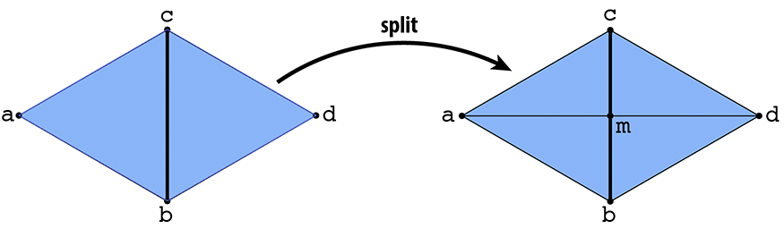
Task 2: Edge Split
In this task you will make a different local modification to the mesh in the neighborhood of an edge, called a split. In particular, suppose we have a pair of triangles (a,b,c) and (c,b,d). The edge (b,c) is split by inserting a new vertex m at its midpoint and connecting it to the opposite vertices a and d, yielding four triangles:
Unlike the previous operation (flip), you will have to allocate new mesh elements this time (e.g., two new triangles, three edges, some halfedges...). Your implementation should:
- Ignore requests to split boundary edges (just return immediately if either neighboring face is a boundary loop).
- Assign the position of the new vertex to the midpoint of the original edge, i.e., the average of its two endpoints (see
Vertex::position). - Perform only a constant amount of work---the cost of splitting a single edge should not be proportional to the size of the mesh!
- Allocate only as many new elements as needed; there should be no "orphaned" elements that are not connected to the rest of the mesh.
- Preserve the manifoldness and validity of the mesh.
This time around, preserving manifoldness is straightforward since an edge split doesn't change the topology of the underlying surface (however, you should still be careful to point all your pointers at the right elements!). To obtain a correct implementation, you might try following the same "recipe" given in the previous task (though clever, clean, and simple alternatives are of course always welcome). To verify that your implementation works correctly, try flipping some edges that you've split, and splitting some edges that you flipped.
Possible extra credit extensions:
Split boundary edges by splitting the interior face and adding a single vertex to the boundary face (see
Face::isBoundary()).Implement edge split for general polygons, rather than just triangles.
Implement vertex split, which is essentially the inverse of the edge collapse you'll implement in the next task.
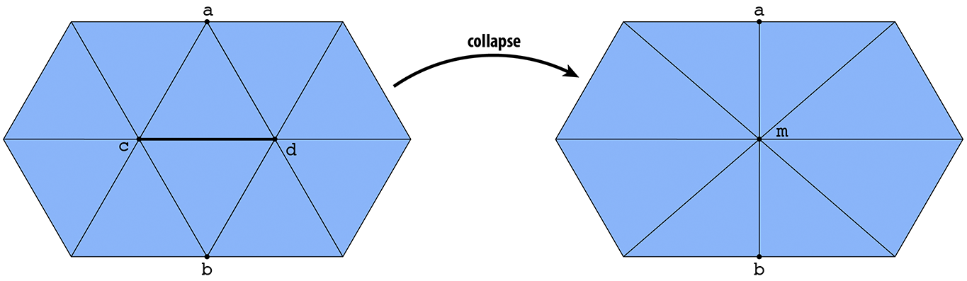
Task 3: Edge Collapse
The third and final operation you will implement is an edge collapse, which contracts an edge to a single point. In particular, suppose we have a pair of triangles (a,b,c) and (c,b,d). The edge (b,c) is collapsed by replacing both vertices b and c with a single vertex m, and replacing triangles (a,b,c) and (c,b,d) with edges (a,m) and (m,d), respectively:
This time around you will need to delete mesh elements, rather than allocate new ones. Deleting elements is especially tricky, because references to these elements may be needed in order to construct the modified mesh---the simplest thing is to simply wait until the end of the edge collapse routine to actually call deleteVertex(), deleteEdge(), etc. Your implementation should:
- Ignore requests to collapse boundary edges (just return immediately if either neighboring face is a boundary loop).
- Assign the position of the collapsed vertex to the midpoint of the original edge.
- Perform only a constant amount of work---the cost of collapsing a single edge should not be proportional to the size of the mesh!
- Preserve the manifoldness and validity of the mesh.
Just like edge flips, there may be situations where an edge cannot be collapsed without violating the manifold property of the mesh; once again, you should think carefully about when an edge can and cannot be safely collapsed. (For instance, what happens if you collapse an edge of a tetrahedron? Do you still have a valid mesh? What if you collapse one more edge after that?)
Possible Extra Credit Extensions:
Implement edge collapse for general polygonal meshes (instead of just triangles).
-
Determine the precise conditions under which an edge collapse will preserve manifoldness, and write a formal proof showing that these conditions are indeed necessary and sufficient.
- Collapse boundary edges by collapsing the interior triangle and removing the collapsed edge from the boundary loop.
Going Further: Tasks that May Potentially Win You Extra Credit:
Implement More Advanced Modeling Tools
Many popular modeling tools are based on the same kinds of local remeshing operations you've been implementing for this assignment. For instance, a very common operation is to "bevel" or "fillet" an edge, to make sharp corners round. Alternatively, faces can be extruded to add more detail to an existing surface. Our basic editor could be turned into a more full-fledged modeling tool by implementing common operations found in packages like Maya or Blender---or inventing your own! (An additional challenge here is that you may have to add some additional functionality to the GUI (graphical user interface), by modifying methods in MeshEditor.cpp, in order to give users an interface to your new editing tools.)
Global Surface Remeshing
The three local remeshing operations split, collapse, and flip are effectively small steps toward upsampling, downsampling, and resampling the surface. In the second half of the assignment, you will combine these operations in various ways to perform a global remeshing of the surface. You can complete the following tasks in any order; they do not depend on each-other.
To make life easier during these remaining tasks, we also ask that you modify your atomic edge operations (flip, split, and collapse) to return the following values (rather than void, as in the original implementation):
-
HalfedgeMesh::splitEdge()- This method should now return a VertexIter pointing to the newly inserted edge midpoint. The halfedge of this vertex should point to one of the halfedges along the edge that was split (rather than the newly inserted edges). This convention will make it easier to implement subdivision. -
HalfedgeMesh::collapseEdge()- This method should now return a VertexIter pointing to the new vertex, corresponding to the collapsed edge. Having a pointer to this value will make it easier to implement quadric error simplification. -
HalfedgeMesh::flipEdge()- This method should now return an EdgeIter pointing to the edge that was flipped (rather than void). In principle, this edge should be the same as the argument toflipEdge(); adding this convention simply makes the interface to these methods more uniform (and is perhaps useful in the future).
Task 4: Upsampling via Loop Subdivision
In image processing, we often have a low resolution image that we want to display at a higher resolution. Since we only have a few samples of the original signal, we need to somehow interpolate or upsample the image. One idea would be to simply cut each pixel into four, leaving the color values unchanged, but this leads to a blocky appearance. Instead we might try a more sophisticated scheme (like bilinear or trilinear interpolation) that yields a smoother appearance.
In geometry processing, one encounters the same situation: we may have a low-resolution polygon mesh that we wish to upsample for display, simulation, etc. Simply splitting each polygon into smaller pieces doesn't help, because it does nothing to alleviate blocky silhouettes or chunky features. Instead, we need an upsampling scheme that nicely interpolates or approximates the original data. Polygon meshes are quite a bit trickier than images, however, since our sample points are generally at irregular locations, i.e., they are no longer found at regular intervals on a grid.
The scheme we'll investigate in this task is called Loop subdivision, which is an approximating subdivision scheme commonly used for triangle meshes. It consists of two basic steps:
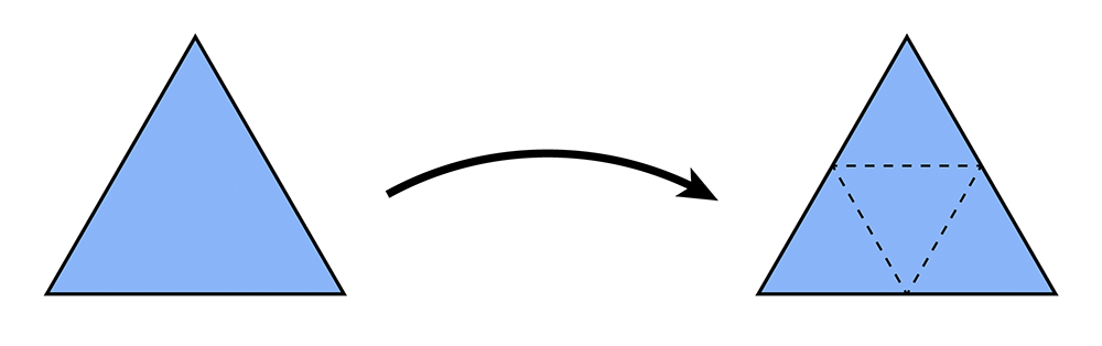
- Split each triangle into four by connecting edge midpoints (sometimes called "4-1 subdivision").
- Update vertex positions as a particular weighted average of neighboring positions.
4-1 subdivision looks like this:
And the following picture illustrates the weighted average:
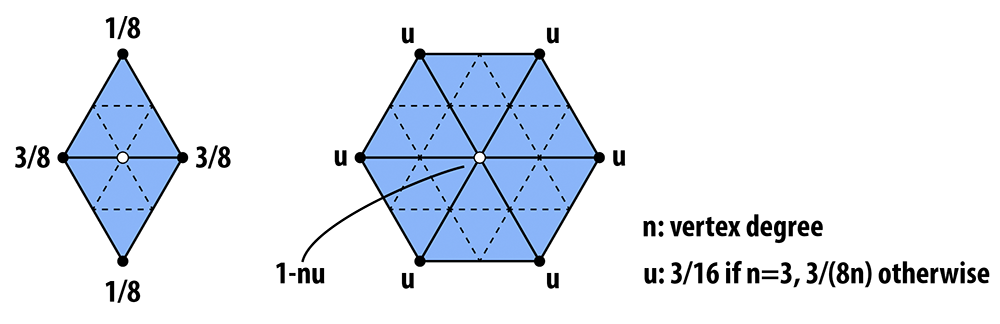
In words, the new position of an old vertice is (1 - nu) + u times the sum of the positions of all of its neighbors. The new position for a newly created vertex v that splits Edge AB and is flanked by opposite vertices C and D across the two faces connected to AB in the original mesh will be 3/8 * (A + B) + 1/8 * (C + D).
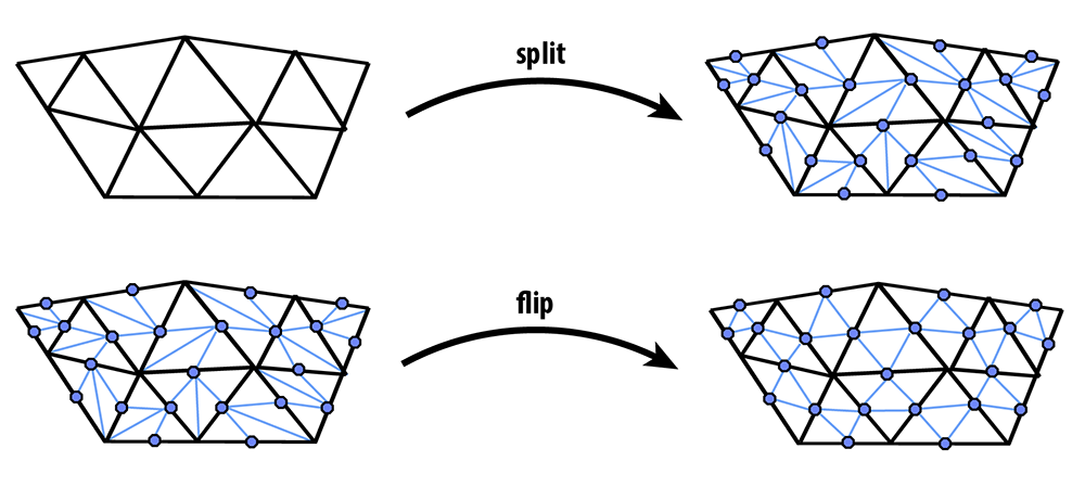
If we repeatedly apply these two steps, we will converge to a fairly smooth approximation of our original mesh. In this task you will implement Loop subdivision using the atomic edge operations you implemented in Tasks 1-3. In particular, you can achieve a 4-1 subdivision by applying the following strategy:
- Split every edge of the mesh in any order whatsoever.
- Flip any new edge that touches a new vertex and an old vertex. Note: Every original edge will now be represented by 2 edges, you should not flip these edges, because they are always already along the boundary of the 4 way divided triangles. In the diagrams below, you should only flip the blue edges that connect an old and new vertex, but you should not flip any of the black new edges.
The following pictures (courtesy Denis Zorin) illustrate this idea:
Implementation
When dealing with a dynamic data structure like a halfedge mesh, one must think very carefully about the order in which mesh elements are processed---it is quite easy to delete an element at one point in the code, and try to access it later (usually resulting in a crash!). For instance, suppose we write a loop like this:
// iterate over all edges in the mesh
for( EdgeIter e = mesh.edgesBegin(); e != mesh.edgesEnd(); e++ )
{
   if( some condition is met )
   {
      mesh.splitEdge( e );
   }
}
Sounds pretty simple, but this routine could very easily crash! Do you see why? The reason is fairly subtle: we are iterating over edges in the mesh by incrementing the iterator e (e++). But since the routine HalfedgeMesh::splitEdge() is allowed to create and delete mesh elements, it might deallocate this edge before we get to increment this iterator to the next edge! To be safe, we could instead write our loop like this:
// iterate over all edges in the mesh
EdgeIter e = mesh.edgesBegin();
while(e != mesh.edgesEnd())
{
   // get the next edge NOW!
   EdgeIter nextEdge = e;
   nextEdge++;

   // now, even if splitting the edge deletes it...
   if( some condition is met )
   {
      mesh.splitEdge( e );
   }

   // ...we still have a valid reference to the next edge.
   e = nextEdge;
}
Note that this loop is just one example---in general, you should think about which elements might be affected by a local mesh operation when writing your loops. Likewise, you can make life easier on yourself by making sure that your atomic edge operations provide certain guarantees. For instance, if your implementation of HalfedgeMesh::flipEdge() guarantees that no edges will be created or destroyed (as it should), then you can safely do edge flips inside a loop without worrying about these kinds of side effects.
For Loop subdivision, we have also provided some additional data members that will make it easy to keep track of the data you need to update the connectivity and vertex positions. In particular:
-
Vertex::newPositioncan be used as temporary storage for the new position (computed via the weighted average above). Note that you should not change the value ofVertex::positionuntil all the new vertex positions have been computed---otherwise, you are taking averages of values that have already been averaged! - Likewise,
Edge::newPositioncan be used to store the position of the vertices that will ultimately be inserted at edge midpoints. Again, these values should be computed from the original values (before subdivision), and applied to the new vertices only at the very end. TheEdge::newPositionvalue will be used for the position of the vertex that will appear along the old edge after the edge is split. We precompute the position of the new vertex before splitting the edges and allocating the new vertices because it is easier to tansverse the simpler original mesh to find the positions for the weighted average that determines the positions of the new vertices. -
Vertex::isNewcan be used to flag whether a vertex was part of the original mesh, or is a vertex newly inserted by subdivision (at an edge midpoint). -
Edge::isNewlikewise flags whether an edge is a piece of an edge in the original mesh, or is an entirely new edge created during the subdivision step.
Given this setup, we strongly suggest that it will be easiest to implement subdivision according to the following "recipe" (though you are of course welcome to try doing things a different way!). The basic strategy is to first compute the new vertex positions (storing the results in the newPosition members of both vertices and edges), and only then update the connectivity. Doing it this way will be much easier, since traversal of the original (coarse) connectivity is much simpler than traversing the new (fine) connectivity. In more detail:
- Mark all vertices as belonging to the original mesh by setting
Vertex::isNewtofalsefor all vertices in the mesh. - Compute updated positions for all vertices in the original mesh using the vertex subdivision rule, and store them in
Vertex::newPosition. - Compute new positions associated with the vertices that will be inserted at edge midpoints, and store them in
Edge::newPosition. - Split every edge in the mesh, being careful about how the loop is written. In particular, you should make sure to iterate only over edges of the original mesh. Otherwise, you will keep splitting edges that you just created!
- Flip any new edge that connects an old and new vertex.
- Finally, copy the new vertex positions (
Vertex::newPosition) into the usual vertex positions (Vertex::position).
If you made the requested modification to the return value of HalfedgeMesh::splitEdge() (see above), then an edge split will now return an iterator to the newly inserted vertex, and the halfedge of this vertex will point along the edge of the original mesh. This iterator is useful because it can be used to (i) flag the vertex returned by the split operation as a new vertex, and (ii) flag each outgoing edge as either being new or part of the original mesh. (In other words, Step 3 is a great time to set the members isNew for vertices and edges created by the split. It is also a good time to copy the newPosition field from the edge being split into the newPosition field of the newly inserted vertex.)
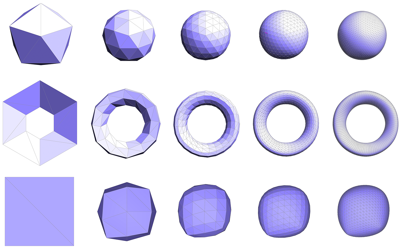
You might try implementing this algorithm in stages, e.g., first see if you can correctly update the connectivity, then worry about getting the vertex positions right. Some examples below illustrate the correct behavior of the algorithm.
Possible Extra Credit Extensions:
Support surfaces with boundary. For this you will need to make sure your edge split operation appropriately handles boundary edges. You will also need to use a different weighted average for boundary vertices; see Boier-Martin et al, "A Survey of Subdivision-Based Tools for Surface Modeling" for more information.
Implement additional subdivision schemes. There are many alternatives to Loop subdivision. Triangle subdivision schemes include Butterfly and modified Butterfly (which are interpolating rather than approximating) and Sqrt(3) (which refines the mesh at a "slower" rate); the most popular subdivision scheme for quadrilateral meshes is Catmull-Clark. There are also special subdivision schemes for handling meshes with high degree vertices, e.g., extraordinary vertices, called polar subdivision.
Implement additional subdivision features. You may have noticed that subdivision generally makes the surface smoother, but of course some surfaces have sharp features that you might like to preserve. Pixar's OpenSubdiv page describes several features of subdivision surfaces you might add to your implementation.
Implement displacement mapping. One reason subdivision surfaces are often used in practice is that they lend themselves nicely to adding lots of geometric detail, via a special texture map called a displacement map. In a nutshell, the fine-level vertices get offset by an amount that is dictated by a bitmap image rather than a fixed subdivision rule. See for instance this paper.
Implement a real-time subdivision editor. Another reason subdivision surfaces are so popular is that they provide an attractive modeling paradigm, i.e., by dragging on the vertices of a coarse mesh, one can interactively manipulate a smooth subdivision surface using a very small number of degrees of freedom. To implement this kind of modeling paradigm in the current tool, you will need to modify the viewer class in
meshEdit.cppandmeshEdit.h. You will likely also need to come up with a more efficient way of evaluating the fine subdivision surface from the coarse control cage. For instance, since the vertex coordinates at each subdivision step are a linear combination of the vertex coordinates at the previous step, you could precompute the final relationship between the original coarse vertices and the final fine vertices. (If you're really feeling ambitious, you could do some of the work in a GPU shader program!)
Task 5: Downsampling via Quadric Error Simplification
Just as with images, meshes often have far more samples than we really need. In this task you will simplify a given model by applying quadric error simplification. This method was originally developed at CMU by Michael Garland and Paul Heckbert, in their paper Surface Simplification Using Quadric Error Metrics. (Looking at this paper---or the many slides and presentations online that reference it---may be very helpful in understanding and implementing this part of the assignment!)
The basic idea is to iteratively collapse edges until we reach the desired number of triangles. The more edges we collapse, the simpler the mesh becomes. The only question is: which edges should we collapse? And where should we put the new vertex when we collapse an edge? Finding the sequence of edge collapses (and vertex positions) that give an optimal approximation of the surface would be very difficult---likely impossible! Garland and Heckbert instead proposed a simple, greedy scheme that works quite well in practice, and is the basis of many mesh simplification tools today. Roughly speaking, we're going to write down a function that measures the distance to a given triangle, and then "accumulate" this function as many triangles get merged together.
More precisely, we can write the distance d of a point x to a plane with normal N passing through a point p as
d(x) = N • (x-p)
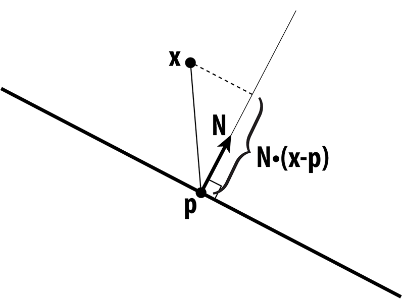
In other words, we measure the extent of the vector from p to x along the normal direction. This quantity gives us a value that is either positive (above the plane), or negative (below the plane). Suppose that x has coordinates (x,y,z), N has coordinates (a,b,c), and let d = -N • p, then in homogeneous coordinates, the distance to the plane is just
u • v
where u = (x,y,z,1) and v = (a,b,c,d). When we're measuring the quality of an approximation, we don't care whether we're above or below the surface; just how far away we are from the original surface. Therefore, we're going to consider the square of the distance, which we can write in homogeneous coordinates as
(u • v)^2 = u^T v v^T u,
where "^T" denotes the transpose of a vector. The term v v^T is an outer product of the vector v with itself, which gives us a symmetric matrix K = v v^T. In components, this matrix would look like
a^2   ab    ac   ad
ab    b^2   bc   bd
ac    bc    c^2  cd
ad    bd    cd   d^2
but in our code framework you can simply compute it using the method outer( Vector4D, Vector4D ) in matrix4x4.h that takes a pair of vectors in homogeneous coordinates and returns the outer product as a 4x4 matrix. We will refer to this matrix as a "quadric," because it also describes a quadric surface.
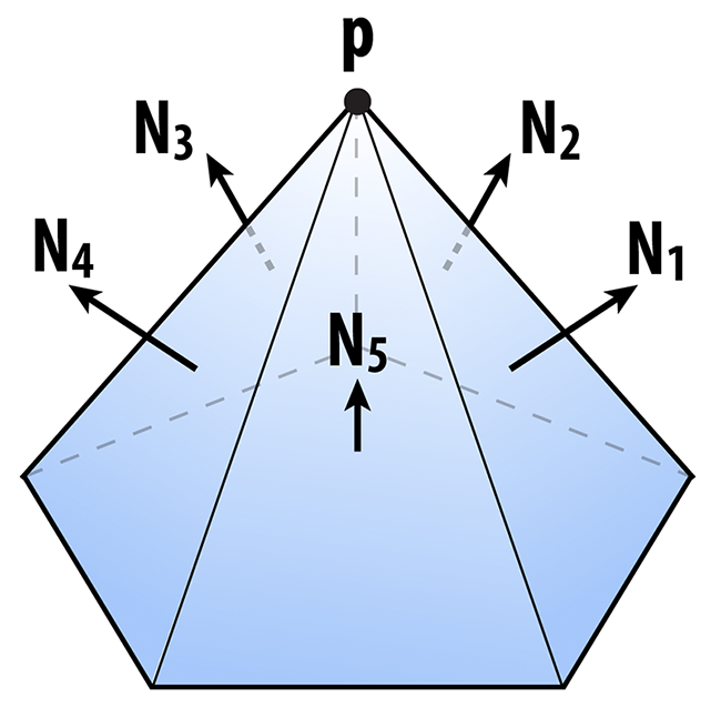
Ok, so the matrix K tells us something about the distance to a plane. We can also get some idea of how far we are from a vertex by considering the sum of the squared distances to the planes passing through all triangles that touch that vertex. In other words, we will say that the distance to a small neighborhood around the vertex i can be approximated by the sum of the quadrics on the incident faces ijk:
K_i = (sum over all faces ijk touching vertex i) K_ijk.
Likewise, the distance to an edge ij will be approximated by the sum of the quadrics at its two endpoints:
K_ij = K_i + K_j.
In your code, we have added a member Matrix4x4 Face::quadric and Matrix4x4 Vertex::quadric to the faces and vertices of the halfedge mesh. The sums above should then be easy to compute--you can just add up the Matrix4x4 objects around a vertex or along an edge using the usual "+" operator. You do not need to write an explicit loop over the 16 entries of the matrix.
Once you have a quadric K associated with an edge ij, you can ask the following question: if we collapse the edge to a point x, where should we put the new point so that it minimizes the (approximate) distance to the original surface? In other words, where should it go so that it minimizes the quantity
x^T K x?
Just like any other function, we can look for the minimum by taking the derivative with respect to x and setting it equal to zero. (By the way, in this case we're always going to get a minimum and not a maximum because the matrices K are all positive-definite.) In other words, we want to solve the small (4x4) linear system
K u = 0
for the optimal position u, expressed in homogeneous coordinates. We can simplify this situation a bit by remembering that the homogeneous coordinate for a point in 3-space is just 1. After a few simple manipulations, then, we can rewrite this same system as an even smaller 3x3 linear system
A x = b,
where A is the upper-left 3x3 block of K, and b is minus the upper-right 3x1 column. In other words, the entries of A are just
a^2   ab    ac
ab    b^2   bc
ac    bc    c^2
and the entries of b are
-ad
-bd
-cd
The cost associated with this solution can be found by plugging x back into our original expression, i.e., the cost is just
x^T K x
where K is the quadric associated with the edge. Fortunately, you do not need to write any code to solve this linear system. It can be solved using the method Matrix3x3::inv() which computes the inverse of a 3x3 matrix. In particular, you can write something like this:
Matrix3x3 A; // computed by accumulating quadrics and then extacting the upper-left 3x3 block
Vector3D b;  // computed by extracting minus the upper-right 3x1 column from the same matrix
Vector3D x = A.inv() * b; // solve Ax = b for x, by hitting both sides with the inverse of A
If you're a bit lost at this point, don't worry! There are a lot of details to go through, and we'll summarize everything again in the implementation section. The main idea to keep in mind right now is:
- we're storing a matrix at every vertex that encodes (roughly) the distance to the surface, and
- for each edge, we want to find the point that is (roughly) as close as possible to the surface, according to the matrices at its endpoints.
As we collapse edges, the matrices at endpoints will be combined by just adding them together. So, as we perform more and more edge collapses, these matrices will try to capture the distance to a larger and larger region of the original surface.
The one final thing we want to think about is performance. At each iteration, we want to collapse the edge that results in the least deviation from our original surface. But testing every edge, every single iteration sounds pretty expensive! (Something like O(n^2).) Instead, we're going to put all our edges into a priority queue that efficiently keeps track of the "best" edge for us, even as we add and remove edges from our mesh. In the code framework, we actually introduce a new class called an EdgeRecord that encodes all the essential information about our edge:
// An edge record keeps track of all the information about edges
// that we need while applying our mesh simplification algorithm.
class EdgeRecord
{
   public:
      EdgeRecord( void ) {}
      EdgeRecord( EdgeIter& _edge );
      // The second constructor takes an edge, and computes all
      // the essential data.  In particular, it computes the sum
      // of the quadrics at the two endpoints, and solves for the
      // optimal midpoint position as measured by this quadric.
      // It also stores the value of this quadric as the "score"
      // used by the priority queue.

      EdgeIter edge; // the edge referred to by this record

      Vector3D optimalPoint; // the optimal point, if we were
                             // to collapse this edge next

      double cost; // the cost associated with collapsing this edge,
                   // which is very (very!) roughly something like
                   // the distance we'll deviate from the original
                   // surface if this edge is collapsed
};
To initialize an edge record for a given edge, you just have to write
EdgeRecord myRecord( e );
In other words, you hand it the edge to be initialized. This record in turn gets added to a priority queue, which stores all the halfedges, sorted according to the cost of collapsing them:
MutablePriorityQueue queue;
queue.insert( e );
If we ever want to know what the best edge is to collapse, we can just look at the top of the priority queue:
EdgeRecord bestEdge = queue.top();
More documentation is provided in the header file MutablePriorityQueue.h.
Implementation
Downsampling via edge collapse is perhaps the most difficult of the three algorithms conceptually, but it is actually not too hard to implement. In this task you will need to implement two methods:
EdgeRecord::EdgeRecord( EdgeIter e ); // initializer for an edge record
MeshResampler::downsample( HalfedgeMesh& mesh ); // downsampling via quadric error simplification
As discussed above, the edge record initializer should:
- Compute a quadric for the edge as the sum of the quadrics at endpoints.
- Build a 3x3 linear system for the optimal collapsed point, as described above.
- Solve this system and store the optimal point in
EdgeRecord::optimalPoint. - Compute the corresponding error value and store it in
EdgeRecord::cost. - Store the edge in
EdgeRecord::edge.
The downsampling routine can then be implemented by following this basic recipe:
- Compute quadrics for each face by simply writing the plane equation for that face in homogeneous coordinates, and building the corresponding quadric matrix using
Matrix4x4::outer(). This matrix should be stored inFace::quadric. - Compute an initial quadric for each vertex by adding up the quadrics at all the faces touching that vertex. This matrix should be stored in
Vertex::quadric. (Note that these quadrics will get updated as edges are collapsed.) - For each edge, create an
EdgeRecordand insert it into one globalMutablePriorityQueue. - Until a target number of triangles is reached, collapse the best/cheapest edge (as determined by the priority queue), and set the quadric at the new vertex to the sum of the quadrics at the endpoints of the original edge. You will also have to update the cost of any edge connected to this vertex.
The algorithm should terminate when a target number of triangles is reached---for the purpose of this assignment, you should set this number to 1/4th the number of triangles in the input (since subdivision will give you a factor of 4 in the opposite direction). Note that to get the best element from the queue you call MutablePriorityQueue::top(), whereas to remove the best element from the top you must call MutablePriorityQueue::pop() (the separation of these two tasks is fairly standard in STL-like data structures).
As with subdivision, it is critical that you carefully reason about which mesh elements get added/deleted in what order---particularly in Step 4. A good way to implement Step 4 would be:
- Get the cheapest edge from the queue.
- Remove the cheapest edge from the queue by calling
pop(). - Compute the new quadric by summing the quadrics at its two endpoints.
- Remove any edge touching either of its endpoints from the queue.
- Collapse the edge.
- Set the quadric of the new vertex to the quadric computed in Step 2.
- Insert any edge touching the new vertex into the queue, creating new edge records for each of them.
Note: Step 2 is highlighted, because these instruction used to erroneously recommend that the pop be done at the end. The pop of the cheapest edge needs to occur before any modifications are made to the queue, because otherwise the edge you are processing might not be the cheapest edge at the end of the 7 step process.
Steps 4 and 7 are highlighted because it is easy to get these steps wrong. For instance, if you collapse the edge first, you may no longer be able to access the edges that need to be removed from the queue.
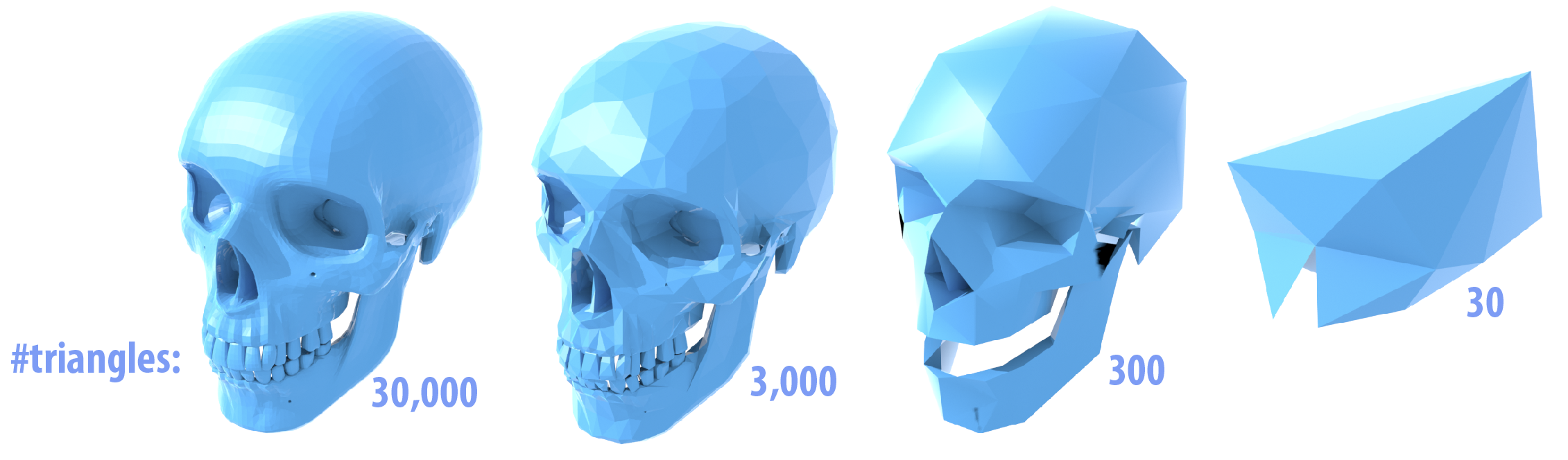
A working implementation should look something like the examples below. You may find it easiest to implement this algorithm in stages. For instance, first get the edge collapses working, using just the edge midpoint rather than the optimal point, then worry about solving for the point that minimizes quadric error.
Possible Extra Credit Extensions:
The original quadric error algorithm allowed not only edge collapses, but arbitrary vertex pair collapses, i.e., two vertices on different connected components of a surface could be joined together. This allows large, complicated meshes with many pieces to be approximated as just a few simple pieces---for instance, a bag of popcorn can be approximated by a continuous surface (useful for rendering from afar!). Can you augment your existing implementation to allow for arbitrary vertex pairs?
In this assignment, we only focus on simplifying the geometry. What if our mesh has other data associated with it (texture, color, etc.)? One can apply similar methods to simplify this richer data as well, basically by incorporating these additional attributes into the quadric.
Modify the quadric error criterion to take other perceptual criteria into account. (E.g., visibility from a certain camera view.)
Iterative edge collapse is not the only way to get a simplified approximation of a surface. A very different approach is variational shape approximation (VSA), which globally solves for a collection of planes that approximate the surface.
Task 6: Resampling via Isotropic Remeshing
Another thing we might want to do with a mesh is keep the number of samples roughly the same, while improving the shape of individual triangles. In this task, we will try to make the mesh as "uniform" as possible, i.e., triangles as close as possible to equilaterial triangles of equal size, and vertex degrees as close as possible to 6. The algorithm you will implement is based on the paper Botsch and Kobbelt, "A Remeshing Approach to Multiresolution Modeling" (Section 4), and can be summarized in just a few simple steps:
- If an edge is too long, split it.
- If an edge is too short, collapse it.
- If flipping an edge improves the degree of neighboring vertices, flip it.
- Move vertices toward the average of their neighbors.
Repeating this simple process several times typically produces a mesh with fairly uniform triangle areas, angles, and vertex degrees. However, each of the steps deserves slightly more explanation.
Edge Splitting / Collapsing
Ultimately we want all of our triangles to be about the same size, which means we want edges to all have roughly the same length. As suggested in the paper by Botsch and Kobbelt, we will aim to keep our edges no longer than 4/3rds of the mean edge length L in the input mesh, and no shorter than 4/5ths of L. In other words, if an edge is longer than 4L/3, split it; if it is shorter than 4L/5, collapse it. We recommend performing all of the splits first, then doing all of the collapses (though as usual, you should be careful to think about when and how mesh elements are being allocated/deallocated).
Edge Flipping
We want to flip an edge any time it reduces the total deviation from regular degree (degree 6). In particular, let a1, a2 be the degrees of an edge that we're thinking about flipping, and let b1, b2 be the degrees of the two vertices across from this edge. The total deviation in the initial configuration is |a1-6| + |a2-6| + |b1-6| + |b2-6|. You should be able to easily compute the deviation after the edge flip without actually performing the edge flip; if this number decreases, then the edge flip should be performed. We recommend flipping all edges in a single pass, after the edge collapse step.
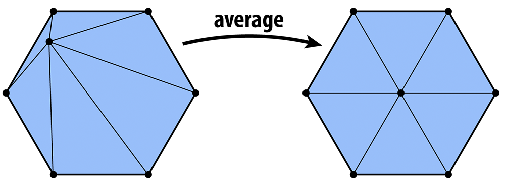
Vertex Averaging
Finally, we also want to optimize the geometry of the vertices. A very simple heuristic is that a mesh will have reasonably well-shaped elements if each vertex is located at the center of its neighbors. To keep your code clean and simple, we ask that you implement the method Vertex::computeCentroid() which should compute the average position of the neighbors and store it in the member Vertex::centroid. The reason this value must be stored in a temporary variable and not immediately used to replace the current position is similar to the reason we stored temporary vertex positions in our subdivision scheme: we don't want to be taking averages of vertices that have already been averaged. Doing so can yield some bizarre behavior that depends on the order in which vertices are traversed (if you're interested in learning more about this issue, Google around for the terms "Jacobi iterations" and "Gauss-Seidel). So, your code should (i) first compute the centroid for all vertices, and (ii) then update the vertices with new positions.
How exactly should the positions be updated? One idea is to simply replace each vertex position with its centroid. We can make the algorithm slightly more stable by moving gently toward the centroid, rather than immediately snapping the vertex to the center. For instance, if p is the original vertex position and c is the centroid, we might compute the new vertex position as
q = p + w(c-p)
where w is some weighting factor between 0 and 1 (we use 1/5 in the examples below). In other words, we start out at p and move a little bit in the update direction v = c-p.
Another important issue here is that if our update direction v has a large normal component, then we'll end up pushing the surface in or out, rather than just sliding our sample points around on the surface. As a result, the shape of the surface will change much more than we'd like (try it!). To ameliorate this issue, we will move the vertex only in the tangent direction, which we can do by projecting out the normal component, i.e., by replacing v with v - (N•v)N, where N is the unit normal at the vertex. To get this normal, you will implement the method Vertex::normal(), which computes the vertex normal as the area-weighted average of the incident triangle normals. In other words, at a vertex i the normal points in the direction
(sum over triangles ijk touching vertex i) A_ijk N_ijk
where A_ijk is the area of triangle ijk, and N_ijk is its unit normal; this quantity can be computed directly by just taking the cross product of two of the triangle's edge vectors (properly oriented).
Implementation
There's very little more to know beyond the description above; this time you should use the following basic recipe:
- Compute the mean edge length L of the input.
- Split all edges that are longer than 4L/3.
- Collapse all edges that are shorter than 4L/5.
- Flip all edges that decrease the total deviation from degree 6.
- Compute the centroids for all the vertices.
- Move each vertex in the tangent direction toward its centroid.
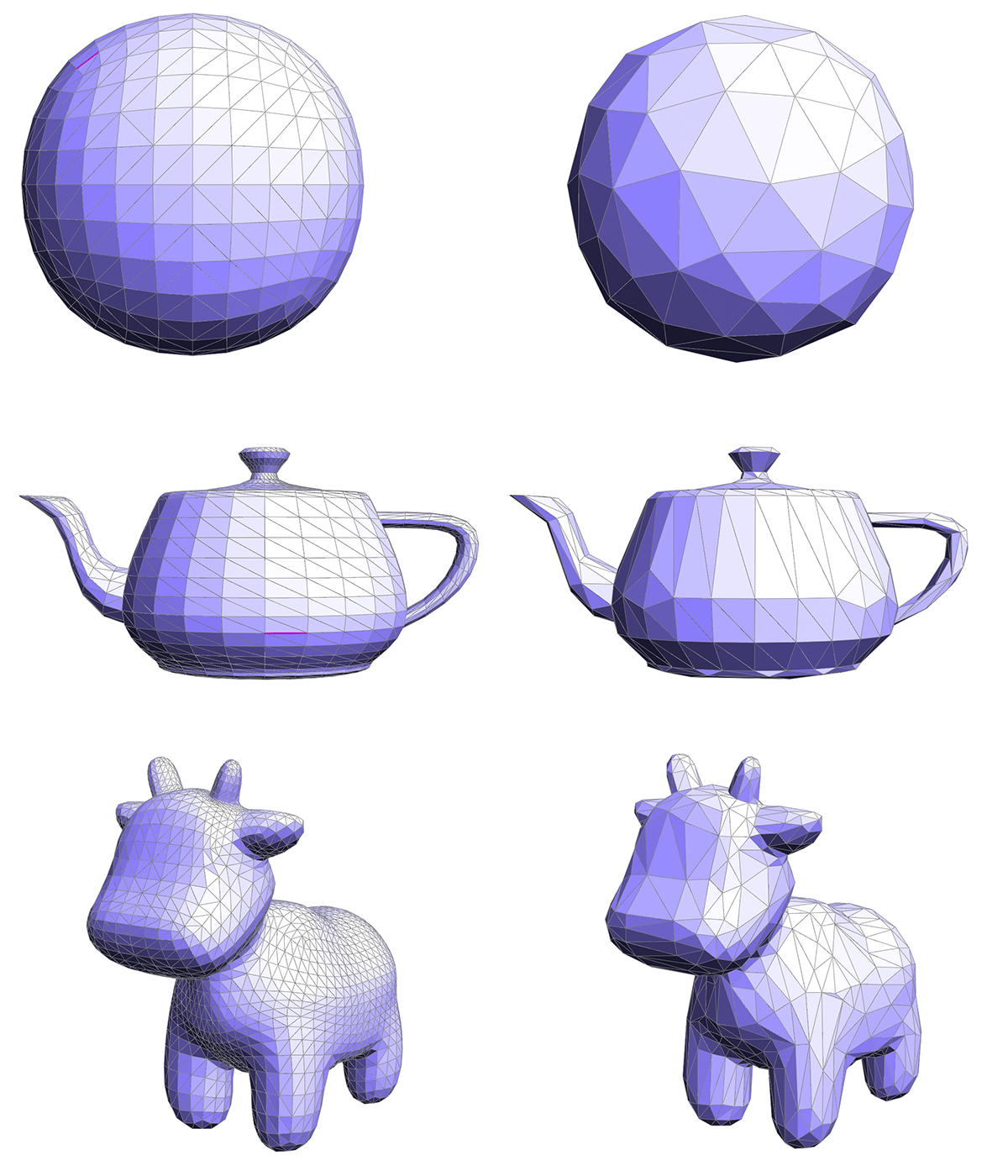
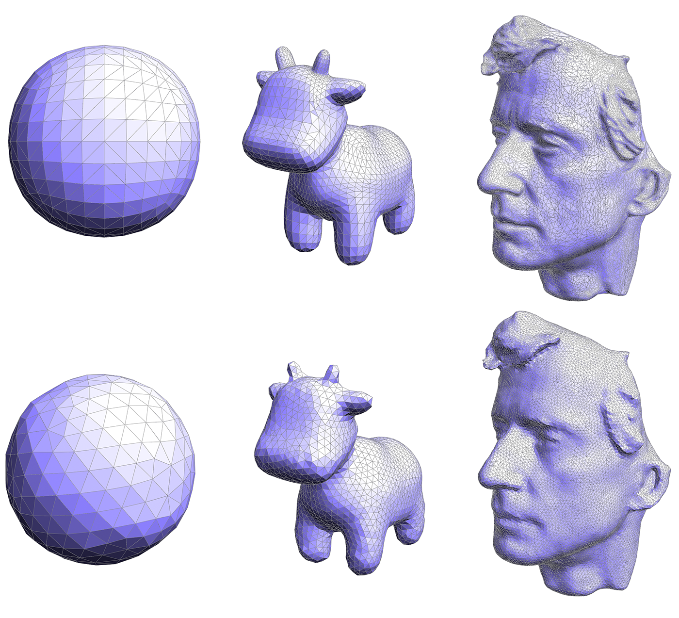
Repeating this procedure about 5 or 6 times should yield results like the ones seen below; you may want to repeat the smoothing step 10-20 times for each "outer" iteration.
What do you think about this algorithm? Does it improve the triangle quality? What about the quality of the geometric approximation? In what situations might this kind of resampling be useful? How might it be improved?
Possible Extra Credit Extensions:
- As hinted at in the question above, this algorithm doesn't deal too well with geometry that has sharp features and large curvatures. A later method by the same author explored adaptation to curvature. Extend your implementation as described in this paper (or based on your own variation of the method).
Putting it all together
Now that you're done with the final operations, do all of your operations work together (upsampling/downsampling/resampling)? What happens if you, say, repeatedly upsample, then downsample, then upsample, then downsample, ... Can you think of other ways of combining or augmenting these meshing operations to get higher-quality resamplings? For instance, how about putting more samples in regions of high curvature? Or placing samples exactly along sharp features, like the corner of a cube? (Nothing needs to be done here---these are just questions to think about!)
As a sanity check, each of your resampling algorithms should run almost immediately (no more than a second or two) on the smaller meshes, and it should be possible to complete remeshing on the larger meshes (albeit more slowly!). If performance is significantly worse than this, you may be iterating over more elements than you really need to, or are mismanaging memory.
Task 7: Creative Image
Using the tool you have just implemented, generate the most interesting/fun/creative model you can by combining upsampling, downsampling, and resampling, with the vertex-drag tool. (If you have implemented additional features, you can use these as well.) We'll show off the best results in class later this semester.
Grading
Your code must run on the GHC 5xxxx cluster machines as we will grade on those machines. Do not wait until the submission deadline to test your code on the cluster machines. Keep in mind that there is no perfect way to run on arbitrary platforms. If you experience trouble building on your computer, while the staff may be able to help, but the GHC 5xxx machines will always work and we recommend you work on them.
Each task will be graded on the basis of correctness, except for Task 7 which will be graded (gently) on effort. You are not expected to completely reproduce the reference solution vertex-for-vertex as slight differences in implementation strategy or even the order of floating point arithmetic will causes differences, but your solution should not be very far off from the provided input/output pairs. If you have any questions about whether your implementation is "sufficiently correct", just ask.
The assignment consists of a total of 100 pts. The point breakdown is as follows:
- Task 1: 14
- Task 2: 14
- Task 3: 14
- Task 4: 17
- Task 5: 17
- Task 6: 17
- Task 7: 7
Handin Instructions
Your handin directory is on AFS under:
/afs/cs/academic/class/15462-s16-users/ANDREWID/asst2/
Note that you may need to create the asst2 directory yourself. All your files should be placed there. Please make sure you have a directory and are able to write to it well before the deadline; we are not responsible if you wait until 10 minutes before the deadline and run into trouble. Also, you may need to run aklog cs.cmu.edu after you login in order to read from/write to your submission directory.
You should submit all files needed to build your project, this include:
- The
srcfolder with all your source files
Please do not include:
- The
buildfolder - Executables
- Any additional binary or intermediate files generated in the build process.
You should include a README file (plaintext or pdf) if you have implemented any of the extra credit features. In your REAME file, clearly indicate which extra credit features you have implemented. You should also briefly state anything that you think the grader should be aware of.
Do not add levels of indirection when submitting. And please use the same arrangement as the handout. We will enter your handin directory, and run:
mkdir build && cd build && cmake .. && make
and your code should build correctly. The code must compile and run on the GHC 5xxx cluster machines. Be sure to check to make sure you submit all files and that your code builds correctly.
Friendly Advice from your TAs
As always, start early. There is a lot to implement in this assignment, and no official checkpoint, so don't fall behind!
Be careful with memory allocation, as too many or too frequent heap allocations will severely degrade performance.
Handle all corner cases properly. Otherwise, your task 4 - 6 will probably suffer from segmentation fault a lot.
Make sure you have a submission directory that you can write to as soon as possible. Notify course staff if this is not the case.
While C has many pitfalls, C++ introduces even more wonderful ways to shoot yourself in the foot. It is generally wise to stay away from as many features as possible, and make sure you fully understand the features you do use.
Resources and Notes
The Half-Edge Data Structure - another tutorial on the halfedge data structure.
OpenMesh - a different implementation than the one used in our assignment, but discusses some of the software design challenges associated with building a halfedge data structure.